Introduction
Well I’m finally getting round to writing up the “Making of the SwitchCam”, the camera that will give the latest DSLRs a run for their money…I jest, but it’s awesome non-the-less!
Turn the clock back 3 years and I had originally planned to set up some CCTV as a home security project (as many others do), however I could not find a suitable solution to power the Pi externally and waterproofing was also a concern. After this project did not amount to much and instead of the parts I’d bought going to waste, I rummaged through my Box of Bits™ and came across a network switch that I had spare.
Suddenly I had a light bulb moment!
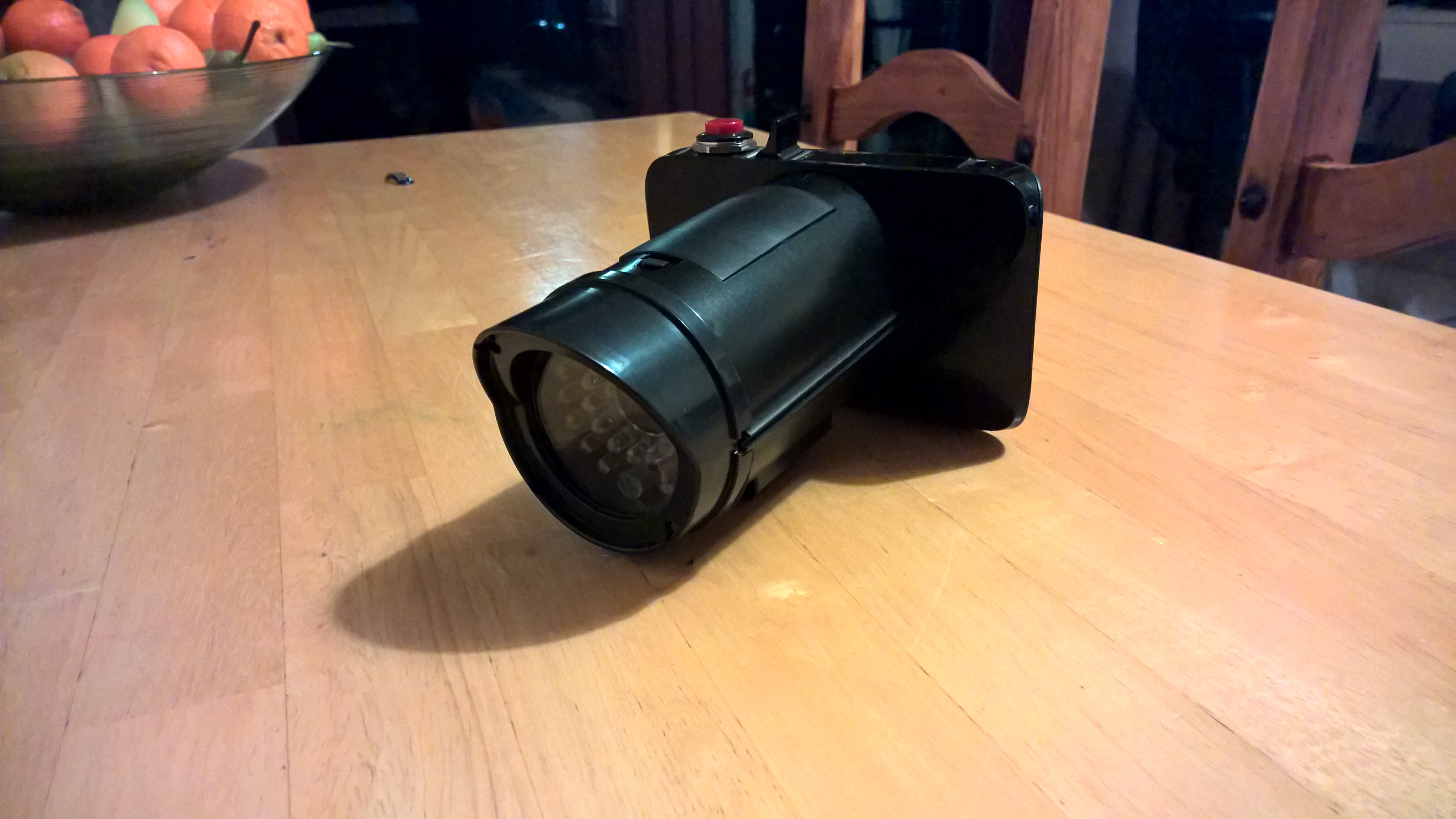
Having the dummy CCTV unit in one hand and the switch in another, by putting them together it looked like a pretty awesome paparazzi camera - to the man cave I went!
Parts list
All prices are correct at the time of writing and don’t include postage:
- TP-Link 5 port Gigabit network switch (TL-SG1005D V7) (£12.95 - Overclockers UK). Note: I originally used the V6 version, but I don’t think there’s any difference between them.
- Dummy CCTV unit (£5.48 - Amazon UK)
- Raspberry Pi Zero W (Pre-soldered) (£12.82 - Pimoroni ).
- Essential Raspberry Pi Zero Kit (£6.00 - The Pi Hut)
- SanDisk Ultra 16 GB MicroSDHC UHS-I Memory Card (£6.39 - Amazon UK)
- Raspberry Pi Camera v2.1 (£24 - Pimoroni)
- Camera mount (£3.00 - The Pi Hut)
- Raspberry Pi Zero camera cable (£4.00 - Pimoroni)
- Red Push Button Switch 3A 250V (Currently unavailable on Amazon UK - Dimensions 24(L) x 18.8mm diameter if you can find an alternative).
- Pimoroni LiPo SHIM (£10 - Pimoroni)
- LiPo batteries 1000mAh (£4.58 - Overlander Batteries)
- Rectangle On/off rocker switch (£0.99 - ebay UK)
- 40 Way female-female ribbon cable 200mm (£2.18 - CPC)
- 40 way right angle pin header (£1.30 - CPC)
- Adafruit PiTFT Plus 3.5” (£45 - Pimoroni)
- RS components 4.2” bezel - manually resized to 3.5” (£9.04 - RS Components)
- JST extension cable (£2 - The Pi Hut)
- Adafruit Micro LiPo charger (£6.30 - Pimoroni)
Total cost: approx. £160 excluding postage.
Tools
- Araldite epoxy resin
- Soldering iron + solder
- Plastic spludger
- Kapton tape
- Philips screwdriver - small one also needed for removing CCTV screws
- Files
- Sandpaper of varying coarseness
Let’s get making
Note: Make sure you’ve earthed yourself correctly before handling any of the ESD sensitive components in this project.
Part 1 - Dismantle switch
So the very first thing you need to do is dismantle the network switch. The back panel of the switch can be removed but you’ll find it’s very stiff on your first few attempts, so grab yourself a thin plastic spludger and start to ease off the back panel, eventually it’ll pop off and you can easily remove the circuitry inside.
Now you’re left with an empty plastic case, great!
Part 2 - Switch carving
Let’s now prepare the Dummy CCTV unit. All we need for this project is the main “pipe”, i.e. we don’t need any of the mounting nor do we need the waterproof plastic that slides on the top. Once you have dismantled the CCTV unit, place the bottom of the pipe onto the shiny side of the switch in the middle and start to draw the outline on it (some tape to help secure it may help here). After you’ve drawn the outline onto the switch, you need to cut out this shape; I began by drilling multiple holes over the area drawn and then filed out the area, finishing up with sanding to get a a nice finish. It is important that you carve out the exact drawing you’ve made, any larger and the pipe will not sit securely in the switch.
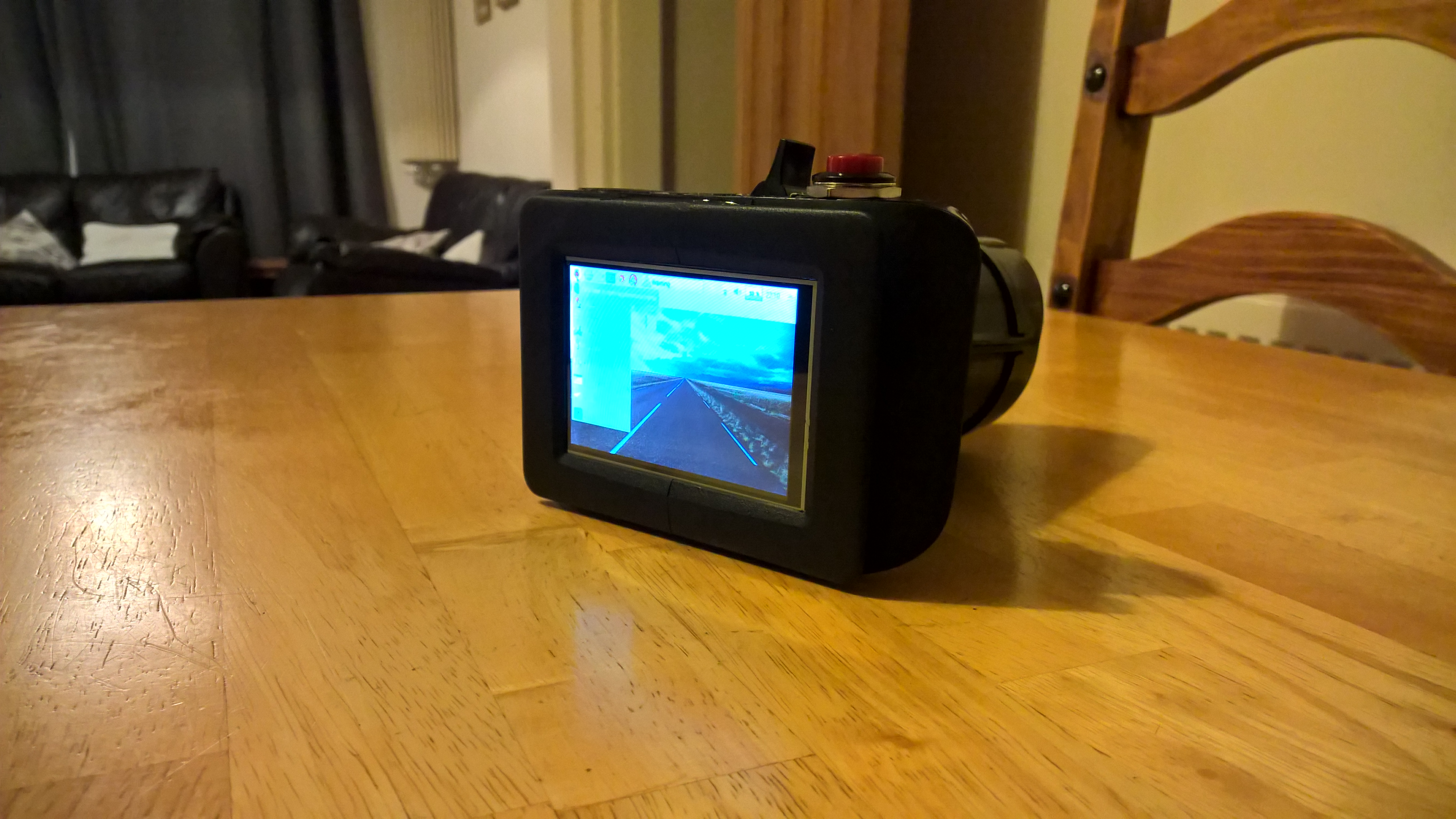
The next stage of carving involves cutting out the shape we need to insert the PiTFT Plus screen used in this project. Measure the dimensions of the screen and draw an outline on the middle of the switch back panel you removed earlier. Once finished, the screen should fit flush in the hole you’ve made and later we’ll connect the screen to the bezel allowing it to protrude slightly giving us more space to play with inside the camera itself.
Part 3 - Button holder
In this section we’re going to start making a home for our red button that we’ll use for taking pictures. If you take a look at the switch and find the hole that originally held the power socket, you’ll see that it is currently a square, we’re going to change that. This part can take a while to get right, but what you need to do is sand that square into a circle that will fit the button inside - you’re looking for a flush fit here. Once you’re happy with the holder, push the button inside and let’s move onto part 4.
Part 4 - Rocker switch
This is a relatively short section, but what we’re going to make use of is the long rectangle space that originally had the switch ports to house our rocker switch. Using some epoxy glue, place the switch on the side closest to your red push button, after around 15 minutes this will be quite secure allowing you to move onto part 5.
Part 5 - LiPo SHIM
The Pimoroni LiPo SHIM is a great addition to your Pi if you’re planning on using LiPo batteries to power it. Installing the unit requires soldering and can be a little fiddly. Before installing onto your Pi, it would be a good idea at this point to solder some wire from your rocker switch to the GND/BAT+. Now you’ve done that we’re ready to solder it onto the Pi!
Position the LiPo SHIM on your Pi’s GPIO header starting from the 3.3/5v pins and solder each pin with a small amount of solder - make sure you don’t have any bad connections or shortages in your soldering.
All being well you should now have a Pi that can be powered by LiPo batteries. Awesome!
Part 6 - Bezel
The bezel you purchased arrived with a 4.2” inner diameter, but we need to change that. Adafruit state the dimensions of the PiTFT Plus 3.5” screen is 84.96mm wide x 56.52mm heigh, so you need to adjust the inner dimension of your bezel to match this. Complete the install of your screen by using the fixtures and fittings provided in your bezel pack. Finally using some epoxy glue, attach the bezel to the switch back panel you carved out earlier - you’ll need a decent amount of glue for this stage, be generous on the top and bottom to create a good seal.
Another neat feature of the PiTFT Plus screen, as we’ll find out later, is that we get a 26 way breakout header that we can make use of!
Part 7 - Camera mount
The purpose of the camera mount in this project is to protect the camera module PCB and also provide a good surface to attach onto the CCTV unit’s fake LED board. Follow the instructions on how to attach the camera module PCB to the mount.
As mentioned, we’re going to be attaching the camera mount onto the fake LED board which can be found inside the CCTV unit after you’ve dismantled it. Using a decent amount of Kapton tape, stick the camera mount onto the fake LED board so the camera module’s sensor is directly in the middle.
Note: I’ve deliberately used Kapton tape here instead of a glue as we may want to remove the camera mount again at a later date.
Part 8 - Connect camera, screen and push button
We’re almost there now, and at this stage you should be able to see what the finished product is going to look like.
Using the Pi Zero camera cable, connect the camera to the Pi.
Before we connect the screen, insert the right angled header into the PiTFT Plus screen pointing downwards, this will give us the extra space required when re-attaching the back plate onto the switch. Now you’ve attached the header, use the 40 way ribbon cable to connect the screen to the Pi Zero - Make sure the cable is the right way round or the screen won’t work when powered on!.
The last stage of this section involves soldering two individual male-female ribbon cables onto your push button. Once you’ve done that, the female end attaches onto the breakout board on the PiTFT Plus screen (I used pins 14 & 16). In order for the button to operate, you’ll need to write some software in your preferred language to handle the button presses - I use the MMALSharp library for interacting with the camera module as well as RaspberryIO to handle the button presses.
For reference:
Part 9 - Connect your battery
A wise man once said “A Pi without any power is about as fruity as toast without jam.”, and he was right! Let’s give your Pi some power! If you remove the battery cover from your dummy CCTV unit, you’ll see it originally supported AA batteries to light up the LED light, so we’re going to make use of this space for our LiPo battery.
The first step you need to do is remove the battery terminals from the enclosure. Once you’ve done this, create a hole in the side of the enclosure facing the screen display.
Next, connect your JST extension cable to the LiPo SHIM board and feed it through the hole you’ve just made in the battery enclosure - the extension cable means we can easily remove batteries from the enclosure without having to open up the camera.
Now go ahead and attach your LiPo battery to the extension cable.
Part 10 - Let’s give this Pi some life!
So we now have a camera…but can’t do much with it at the moment. Download Raspbian and burn it onto your SD card. Before we power on the Pi, you may have realised that the screen won’t work straight out of the box, so we need to hook the Pi up via HDMI to a monitor/TV temporarily.
We’ve reached the moment you’ve all been waiting for, let’s turn our rocker switch to the on position.
Lights, camera, action!
On first boot, we want to go through the usual setup steps such as updating & upgrading, but we also need to enable the camera module and increase the memory split - 128Mb should be enough for light usage.
Let’s get this screen working - head over to Adafruit’s website and follow the instructions on how to download and install the drivers - Make sure you install PiTFT as HDMI Mirror.
Part 11 - Finishing up
Well this is it, we’ve set up everything we need for the SwitchCam project. Congratulations! I hope you’ve had as much fun making it as I did, it certainly had its ups and downs, and at one point I questioned whether it was even possible to fit so much hardware in such a small space!
To complete the project, you need to assemble any parts that are still left, it’s a bit of a squeeze but it does all fit, I promise!
You’ll also notice there’s an open space next to your on/off switch that’ll need filling up - I used some matrix display plastic that’s used in digital LED displays but you’re free to use whatever material you wish, some super glue round the edges finished off with some epoxy afterwards will do the trick nicely.
Special thanks
Huge thanks goes out to my dad for all the help he provided whilst doing this project. He helped keep me on track and offered a lot of assistance on areas I wasn’t as strong in (soldering - it’s a dark art!).
Gallery